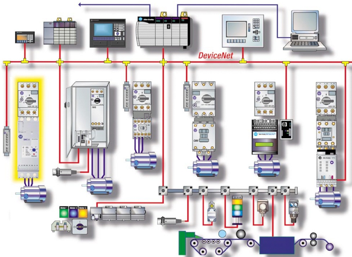
Imagine this: you’re tasked with getting a critical piece of equipment up and running, and the only thing standing between you and success is the daunting task of deciphering a complex Allen Bradley wiring diagram. Fear not, fellow industrial enthusiast! Understanding these diagrams is the key to unlocking the potential of your motor starters, and with the right knowledge, even the most intricate connections can become clear as day.

Image: mydiagram.online
Allen Bradley motor starters are the workhorses of industrial automation, controlling the power to electric motors and ensuring smooth, reliable operation. But behind the simplicity of a pushbutton start and stop, lies a web of electrical connections that can be intimidating for the uninitiated. This article will demystify the art of reading Allen Bradley wiring diagrams, empowering you to confidently connect, troubleshoot, and maintain your motor starters with both safety and efficiency in mind.
Understanding the Basics: Anatomy of a Motor Starter
Before diving into the intricacies of wiring diagrams, let’s first understand the fundamental components of a typical Allen Bradley motor starter. These diagrams are like maps, guiding you through the interconnected parts that make this system work:
- Contactor: The heart of the motor starter, the contactor is an electronically controlled switch that opens and closes the motor circuit, effectively turning the motor on and off.
- Overload Relay: Your motor’s guardian angel, the overload relay protects it from harmful overcurrents. When things get too hot in the motor windings, this relay trips, halting the action to prevent damage.
- Control Circuit: This is the brain of the operation, processing signals from pushbuttons, sensors, or other control devices to tell the contactor when to engage or disengage.
- Power Circuit: The main artery of the system, the power circuit carries high-voltage electricity from the source to the motor.
Deciphering the Language of Allen Bradley Wiring Diagrams
Allen Bradley wiring diagrams use a standardized set of symbols and conventions, designed for clarity and consistency. Think of them as a visual language that any electrician can understand, no matter their native tongue.
- Line Diagrams: These diagrams focus on the flow of electricity, showcasing the path that power takes from source to load. They are ideal for comprehending the core connections and functionalities of the system.
- Ladder Diagrams: A prevalent choice in industrial settings, ladder diagrams represent the electrical circuit as a series of rungs connected by “rails.” Each rung depicts a parallel path for current, using symbols to indicate switches, relays, and other elements. This method is intuitive for visualization and troubleshooting, allowing you to trace the signal flow and identify potential problems with ease.
- Schematic Diagrams: Offering a more detailed approach, schematic diagrams depict the physical layout of components and their internal wiring configurations. They are valuable for in-depth analysis and understanding the precise connection points within each device.
Mastering the Elements: Interpreting Symbols and Components
Each symbol on an Allen Bradley wiring diagram carries specific meaning, crucial for interpreting the desired function of the components. Get acquainted with the key symbols you’ll encounter:
- Contactors: Represented by a square with a letter, e.g., “CR” for contactor relay, or a number, e.g., “1” for contactor number one.
- Pushbuttons: Depicted as a circle with a specific letter indicating their function, such as “SB” for start button, “NB” for normally open button, and “NC” for normally closed button.
- Overload Relays: Usually shown as a circle with the letter “OL” and a number, e.g., “OL1” for overload relay one.
- Limit Switches: These sensors detect the position or movement of machinery, usually depicted as a circle with the letters “LS” and a number to identify the specific switch.
- Thermal Overloads: Indicated by a circle with the letters “TO” and a number, these protect motors from excessive heat by interrupting the circuit.

Image: engineengineberg.z19.web.core.windows.net
Safety First: The Importance of Proper Wiring
The safety implications of incorrect wiring cannot be overstated. A single miswired component could lead to catastrophic consequences, including electrical fires, equipment damage, and even personal injury.
- Understand the Voltage Rating: Always match the motor starter’s components with the voltage of your power supply. A mismatch could result in overheating, burnout, or worse.
- Inspect Wires Thoroughly: Look for any signs of damage, corrosion, or loose connections. Damaged wires are a fire hazard and must be replaced before energizing the system.
- Ensure Proper Grounding: Grounding protects against electrical shock. Make sure all components are properly grounded and that the grounding wire is intact.
Troubleshooting Tips: When Things Go Wrong
Despite the best efforts, problems can occur. Knowing how to troubleshoot common issues can save you time and frustration:
- Use a Multimeter: This essential tool can help you measure voltage, current, and resistance to diagnose problems with specific components.
- Check the Overload Relay: If the motor won’t start, a tripped overload relay could be the culprit. Ensure the relay is reset and that there are no signs of damage or overheating in the motor windings.
- Verify Control Circuit Connections: Pay close attention to the control circuit, checking pushbutton contacts, limit switches, and sensor wiring for any breaks or defects.
- Inspect for Loose Connections: Over time, connections can loosen, creating resistance and affecting the overall performance. Tighten terminals and connections to ensure proper current flow.
Allen Bradley Wiring Diagrams Motor Starter
Allen Bradley Wiring Diagrams: Your Key to Success
Understanding Allen Bradley wiring diagrams is a valuable skill for anyone working with industrial automation systems. From ensuring safe operation to troubleshooting potential problems, mastering these diagrams empowers you to confidently manage your equipment and achieve optimal performance.
Remember, the key to success lies in approaching these diagrams with a methodical mindset, paying attention to detail, and utilizing the right resources for support. With practice and a willingness to learn, you’ll soon be navigating these visual guides with ease, unlocking a world of possibilities in the realm of industrial automation.


